3D Printing and Variations
Not all 3D printing is created equal, but most of it is cheap so that’s great.
In general, FDM printing is the hobbyist’s go-to standard. Plastic filament is extruded out through a nozzle to create a line of plastic. The lines are connected together and stacked to form a 3-dimensional object. However, the lines and layers of lines aren’t always completely connected. This can result in weak points and rough surfaces in the prints. The plastic that makes up the prints is often optimized for looks rather than structural performance. The plastic will often deform over long times of physical stress, a quantifiable term known as creep.
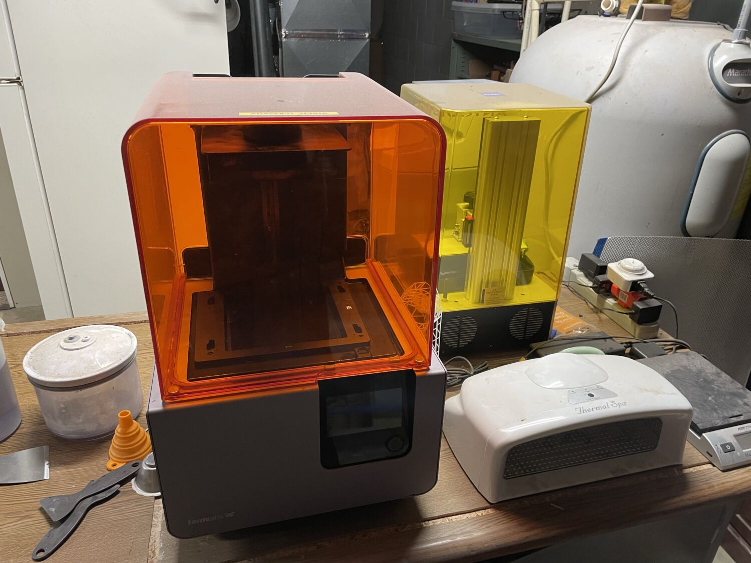
DLP and SLA are the other common forms of hobbyist 3D printing. A vat of liquid resin is cured by ultraviolet light in the bottom forming a layer all at once. Then a platform pulls this layer up, and more resin flows underneath. Then this layer is cured to form another layer. Resin printing has distinct advantages compared to FDM like high resolution and accuracy. The resin being liquid means there are no lines and layers in the part, the part is equally strong in all directions. This is known as being an isotropic material. Furthermore, engineering resins, that are tough, rigid, or flexible can be used to get desired parts, and they often list the mechanical properties of the material. These include yield strength, Young’s modulus, and creep. Young’s modulus is very important in the laser cutter because it represents the ability to withstand deformation under load. The precise optics in the laser can’t drift over time, or while in movement which is affected by the modulus and creep.

Finite Element Analysis
Now that the material for custom parts has been decided, I can test to see if the designs are up to the tasks in CAD. Autodesk Inventor has a simulation tab where users can apply loads and test their designs. The main system that powers these simulations is Finite Element Analysis or FEA. It is the system where a complex solid is broken down into small elements and acted upon by forces. There are tons of complex linear algebra and calculus that allow the system to run, but for the user, it’s a very easy program to use.
FEA In Use

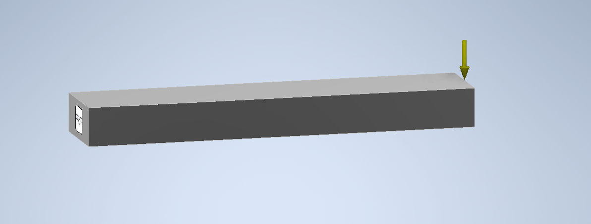
This is all it takes to simulate force onto this rectangular prism. I applied a fixed constraint to the left face and applied a downward force of 50 pounds onto the right top edge.
Inventor will break up the solid into a mesh, and then calculate the force, stress, and deformation on it. Depending on the shape, calculation can take a lot of processing power and time.

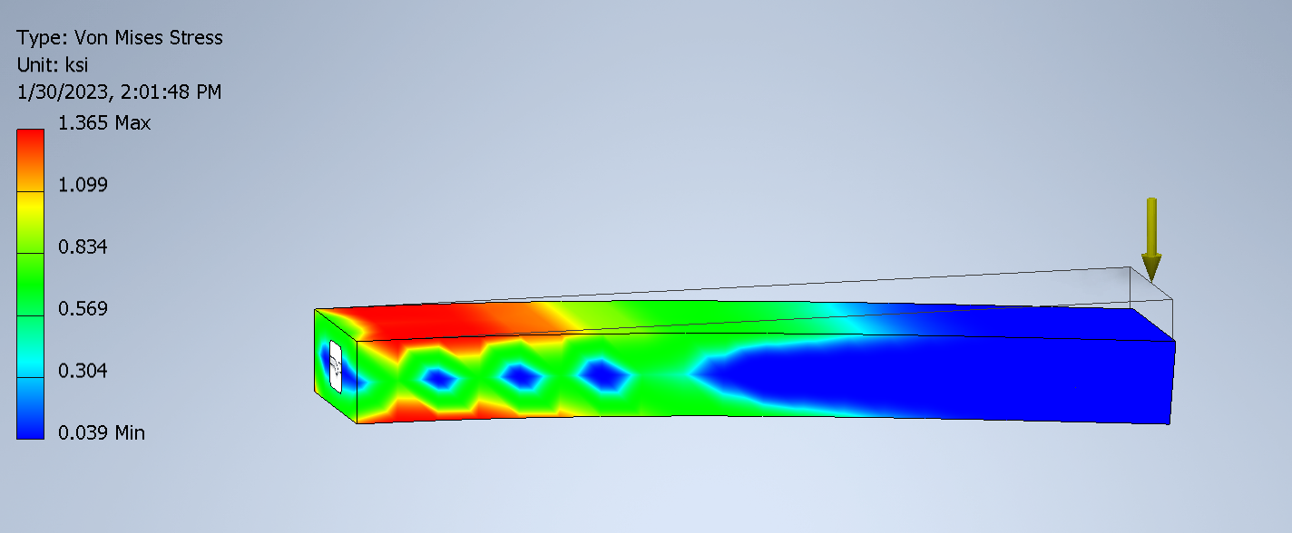
The simulation finishes and a variety of graphs are shown. The Von Mises Stress graph shows the severity of force within the prism. Areas closer to red have more stress and are consequently more important to the shape resisting deformation.

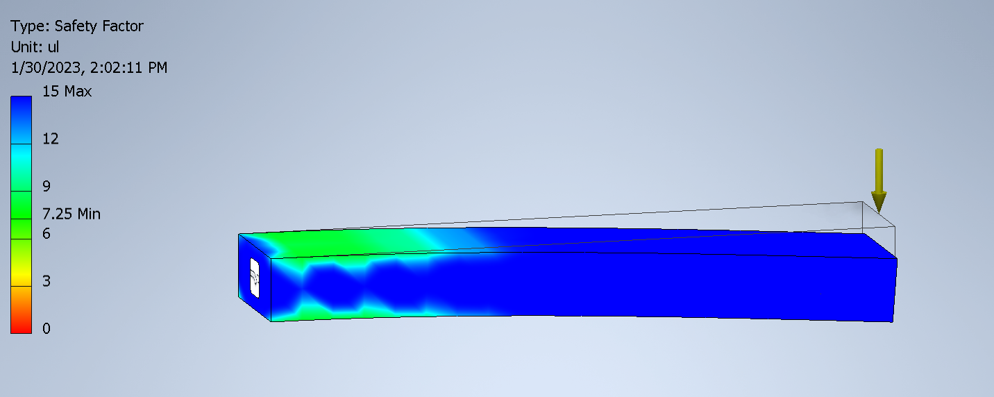
Another very important graph is the Safety Factor. This shows how many times over the given load can the part handle. The minimum on this part is a 7.25x safety factor. It can handle a 7.25 * 50 lbs load, or approximately 360 pounds before failing. This is very dependent on the entered physical properties, and incorrect inputs can result in distortions. It is very important to not rely on this if the breaking of a part can injure or kill a person. That being said, elevators are designed with a 10x or more safety factor, and typical parts are designed to be 1.5x.
Analyzing Actual Parts
Using the power of Inventors FEA, it’s time to see whether the laser cutter parts are strong enough for their applications.
The Idler Pulley Bracket
Below is the full Inventor report, click here to skip to the TLDR.
So what does this all mean? The first couple of images highlight the constraints and forces. The bolt holes are all held in place, mimicking bolts, and the axle hole has axial and bearing forces applied. This simulates belt tension in the bearing force and tests to ensure the bracket won’t fail if it’s pushed from the side as well.
The next area is the Von Mises Stress, it is a culmination of various stress and displacement factors, but essentially boils down to more stress means more critical to the part. Areas of high stress indicate critical parts of a design and may lead to failures if over-stressed.
Further down, the analysis highlights the displacement of the part. Even though we wish they weren’t everything is squishy to some extent, so the displacement is calculated to show how much a part would move under that force.
After that is the strain and safety factor, with the latter being the most important to us at this point. The analysis highlights that the part has a safety factor of 7.45 ul, meaning that it is 7 times stronger than the expected loading. This helps to ensure the part can handle unaccounted-for loads, plus resist creep in the long run.
Other Parts
I won’t bore you with the analysis of every single 3D-printed part, but I did run simulations on them all. The most notable one was the bed ACME nut bracket that supported the bed from a threaded rod. The simulation shows the part was likely to shear if anything was dropped on the table making a force above 100 lbs. This might happen more than you’d think, so out of precaution the main body of the bracket was thickened to support a static load of 100 lbs per bracket with some safety factor.
Other Project Updates
See the rest of the project posts below:
What more do we offer?
Discover other great products and stories: